Greasing
Three different, tried and tested lubrication variants using lubrication holes or grease relief holes are shown below and can be used depending on the space available. There is no risk of leakage in from the outside as the holes are filled with grease.
General information about greasing:
Laminar rings that are greased have a better sealing effect than dry-running rings. A greased laminar ring seal is required in particular when sealing against splash water, dirt and scale. Grease pressed in from the bearing has difficulty passing a laminar ring seal. Grease overpressure is only released when the surrounding components move or rotate over the rings. It is better to fit grease relief holes. Appropriately arranged holes – preferably four around the circumference with a diameter of 3 to 5 mm – supply the rings with grease, including via the groove base, and also enable easy replacement of used grease with new grease.
Recommendations about the choice of lubricant and information about lubrication intervals cannot be provided. The type and quantity of a suitable lubricant must be determined and specified by the customer in accordance with the operating conditions such as rotation speeds, operating temperatures, degree of contamination and environmental conditions. Roller bearing manufacturers and lubricant manufacturers can provide information in this connection.
Please note: The “FK 5 HFL” ring types are an exception when it comes to greasing. They must be installed dry and without any additional lubricants. The surrounding components that come into contact with the laminar rings must not be greased either. Due to the high operating temperatures, the lubricants tend to carburise and the laminar rings fail.
Variant 1
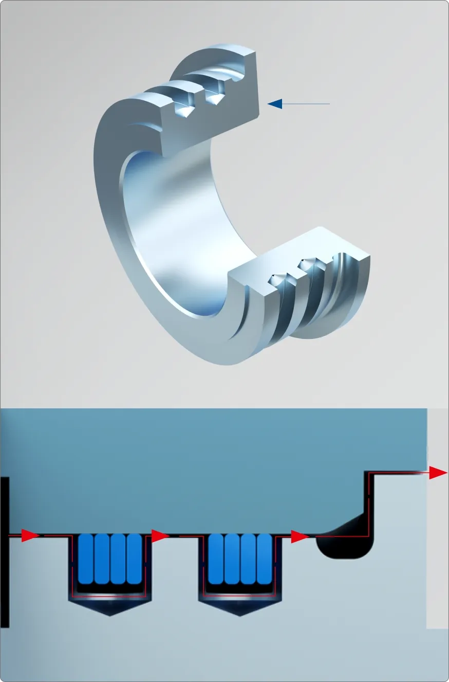
Grease relief holes provided vertically in relation to the groove base, four per groove, 90° apart around the circumference. The bore diameter depends on the groove width. The grease pressed in on the bearing side can enter next to the rings and escape upwards past the rings.
Variant 2
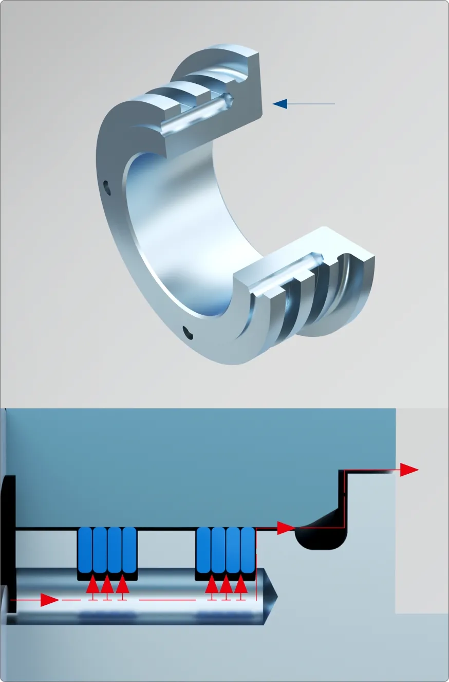
Grease relief holes provided horizontally in relation to the base of the groove, four per groove, 90° apart around the circumference. The bore diameter should be between 3 and 5 mm. The grease pressed in on the bearing side can escape under the rings (groove base diameter) and upwards past the rings.
Variant 3
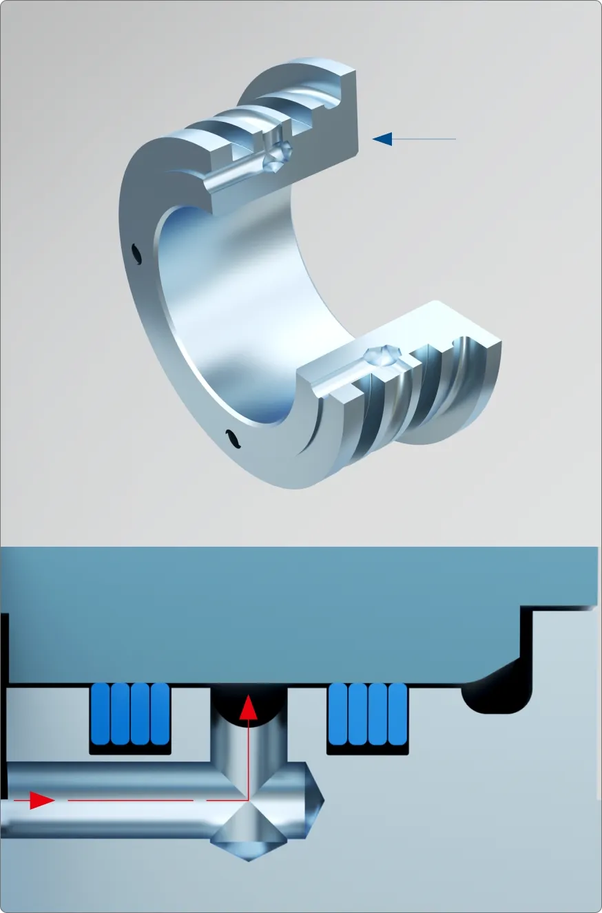
This lubrication design is a combination of the two preceding variants 1 and 2. Here, a so-called “grease chamber” is created between the two sealing ring sets. Experience has shown that this can then hold the grease in the grease groove for a relatively long time and thus optimise the sealing effect.